Final Project

Documentation: From Proposal to Presentation

Click on the dropdown arrows to read more about each stage of the final project!
Project Proposal: Mortar & Pestle

A very popular garnish used in Vietnamese cuisine is crushed peanuts. It adds a special nutty flavor to the dish. Without these crushed peanuts, the dish lacks depth. Despite its important role in Vietnamese cuisine,the garnish requires a time consuming process to make. In large batches (if the dish is supposed to feed more than 10 people at once), crushing peanuts can take upwards to two hours using the mortar and pestle. Therefore, a possible final project is to develop a mortar and pestle machine that can crush peanuts.

A Vietnamese dish called Bún Thịt Nướng Chả Giò that uses peanuts as a garnish
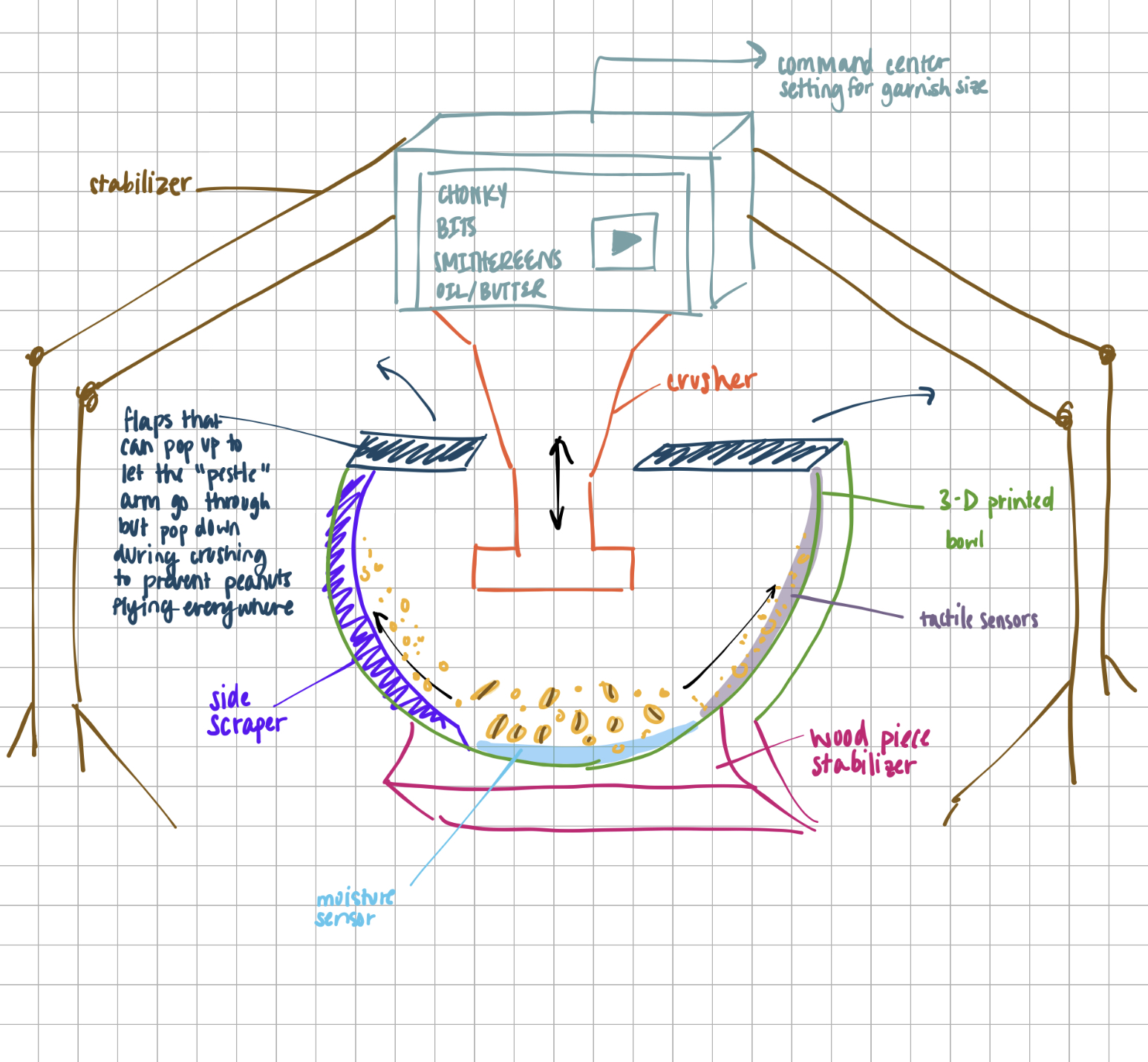
The machine will potentially include a "pestle" robot arm, a 3-D printed fish bowl, sensors at the bottom of the fish bowl, mortar scraper, application to send garnish orders, and wireless connection to send the garnish order.

Even though the garnish is crushed peanuts, some dishes may call for more chunkier bits while other dishes call for smaller pieces. While I don't have the skills to make a machine learning algorithm for this machine to recognize the size of the peanuts as they are being crushed, we can have a proxy through a sensor for wetness/moisture. As a the peanuts are being crushed, finer peanuts start to leak peanut oil. So the sensor at the bottom will tell the machine if it has reached the desired finess of the crushed peanuts. When you crush peanuts using a pestle, over time, there will be a wall of crushed peanuts that get stuck to the sides, and those do not receive crushing action, which is located in the center. Therefore, there will also be sensors that can identify if something is stuck onto it. If yes, then the machine will have a scraper, like a windshield wiper, that scrapes the inner sides of the "mortar" so that those peanuts get placed back into the center.

A sketch of the mortar & pestle machine

Stage 3: Final Project

This final project was filled with many bumps from start to finish. The first was that I had to completely change my product design.
GEARS:
After my minimum viable product was able to move up and down, I went with the assumption that my final product will look similar enough to it except with the ability to hold up a pestle looking object. My MVP was centered around a plate with a motor stepper attached underneath the plate. The stepper motor was attached to a lead screw that had a guiding rail. The idea was that a pestle could be attached somewhere along the lead screw. Come closer to the project’s due date, I realized two things: There isn’t a way to print a pestle that could generate enough force when going up and down to crush peanuts. 3D prints are very light. Two, if I am using a weight instead, my current design would be unable to move it because it’s actually pretty weak. The motor can’t supply that much force by itself.

So, I had to redesign my project. Going back to the drawing board, I placed in some gears. How gears work is that they can amplify the force that was initially sourced from. Here is a quick physics lesson:

physics gear ratio


From this equation, if the gear ratio is higher, than there will be more torque. For that reason, I have a 3:1 ratio between my gears. Essentially with enough gears that is of the right size (high gear ratio!) and thickness,I can move a weight. Based on my calculations, I need about 5 gears, 3 big ones module 5 with 30 teeth, and 2 small ones module 5 with 10 teeth. If the gears are the same module, they won’t be compatible with each other and won’t spin.

So, the first thing I did was print out some gears. I 3D printed them using the GF gear generator plug-in.

Prusa print
3d print gear

The details of my gears are as follows:

Small one:
Big one:
3d print gears

I was determined to use up all the excess colorful filament that have sitting around, so I had a pretty colorful set of gears. I should have learned this during 3d printing week, but now I can unload and load a printer with filament like an expert.

At this point, I was still under the assumption that I could just stop the stepper motor and let gravity take over and pull the weight down. However, I realized that the gears are harder to move, the further we get from the closest gear attached to the motor. This farthest gear is able to pull up the weight and overcome the force of gravity, and there is enough of friction between my rack and the gear so that they don’t slip should the motor get shut off.

So I cannot just shut down the motor, but I have to actually reverse its direction. Therefore, I realized my gears should be helical because they handle reversal of direction much better than spur gears. Helical gears can also support more weight.

Along with the gear, I also need to make the rack. The gear has to be moving something up and down to crush my peanuts, so there must be a surface that it is pushing. I made a rack using the GF gear generator plug-in.

3d print rack

These are my dimensions:
This is just the rack, which does not include a place to insert the string that will be in direct contact with the weight. I realized I would need to screw this onto a wooden surface that is a little bit bigger than the rack and then drill a hole where the string will be pulled through. The rack must designed with some screw holes so that it can be stuck onto the wooden board.

rack with holes

FRAME:
The frame of this project is a big undertaking (quite literally). I designed the smaller gear to be on top of the larger gear because I want to be as little space between the gears as possible. A pair of gears took about 7 hours to print. I set them as an overnight print as a courtesy to other students also using the 3D printers.

I needed to make a frame that is large enough for my ginormous gears, and I need to find a place to attach some sort of string to my gear to pull up the weight.

I completed my frame with aluminum extrusions. There were various sizes, but I needed the extrusions to be as long as possible. The longer they are, the taller height my weight can reach later. However, it was difficult to find aluminum extrusions of equivalent sizes. It was going to take too long to cut it by hand, so I headed to the Lyman Machine Shop and cut my extrusions. It took less than 10 minutes with the machine. If I had done it by hand, it would have taken at least 4 hours because extrusions are tough, and I don’t hit the gym as often as I should.

To put the aluminum extrusions together, I used corner brackets. I discovered fab lab has this incredible thing called a T nut, and used that for the corner bracket alongside 5 mm x 10 screws. We were running low on those types of screws, so I was hunting everywhere to get the screws I needed.

corner bracket

T nut

Once I put the aluminum frame together, I knew I needed two shafts where my two rows of gears will go. These shafts were 8 mm in diameter, so I printed some bearing support 3D designs to attach the shafts to the aluminum frame. The print filament messed up my prints though, and when I inserted my bearing supports, the prints broke. As a result of that, I printed new ones.

Putting together the frame

MORE GEARS:
Because one pair of gear took super long to print (7 hours), I decided to attempt at making it take less time by decreasing the thickness of the gear, which I had originally set for 20 mm. I didn’t want to do this in the first place because I want my gear mechanism to be strong and seamless. If it is too thin then the chances of the gears slipping from one another is higher and there is lower support. Thicker gears means more surface area, so the gears cannot miss each other. When push comes to shove though, I know I don’t have much more time, so I halved the thickness of the tear to 10 mm.

When it finished printing, and I put the two prints together, I saw the problem I was exactly expecting. The two sets (thinner and thicker) have to be positioned very exactly or else the divot that is a part of the chevron looking pattern of the helical gear with get jammed up with the slant part of the track of the other helical gear. Because of this problem, I went back to printing the gears at full 20 mm thickness. I want a seamless operation.


This time I put on some fun embellishments, representative of my peanut crusher purpose. I copy and pasted a graphic of some peanuts into inkscape and trace the bitmap to then export as a dxf file before importing the dxf file into Fusion. I put this on the surface of my big gear.

STEPPER MOTOR:
Putting together the frame was tedious because of all the screwing. The gears took a long time to print, and the motor was absolutely not fun to work with. I used a stepper motor and a coupler that would fit an 8 mm shaft. The stepper motor will turn the shaft and turn the smallest gear. This gear is not positioned in the other two rows of gears. It will be by itself on the shaft connected to the stepper motor. It is however, touching the first gear of the two rows of gears, so once it starts turning, all gears will be moving regardless of what row they are on.

To get the gears to not move around on the shaft, I used these rubber bits that were super tight. So tight that to put them on, I eroded the skin of my fingertips due to the friction that was generated. #sacrificewasmade. They were kind of like a corset but for gears. I needed a rubber bit before and after the set of gears. I also put the rubber bits outside the bearing support on the shaft to prevent the shaft from slipping off the bearing support once the machine is in motion.

The stepper motor worked at first. Here is a picture of the circuit board.

breadboard


Afterwards… it just stopped working. I then spent the next few hours troubleshooting my stepper motor problem. At one point, I gave up on my stepper motor, and I switched to a DC motor. I originally did not want to use a DC motor because I didn’t think it would be strong enough to turn my machine. I was right. When I made the switch, the DC motor could spin a shaft but when that shaft is connected to a whole set of 7 gears, the machine did not move a single bit. Therefore, I had to switch back to a stepper motor and really try to make it work.

It was not until Kassia came in the morning that I was actually able to make my stepper motor work. We constructed a new circuit using completely new parts except the stepper motor and the Arduino Uno. Turns out, the stepper motor was working. The issue lies in the wires, the esp32, or the stepper motor driver. In this new circuit board, we changed out the arduino uno to the esp32, and it worked as well, so the esp32 was not the problem. The biggest issue was that my stepper motor driver had stopped working and we realized this after exchanging the stepper motor driver that we knew worked to the stepper motor driver I was using. Then, we checked the wires. With the new stepper motor driver, I had to hold down my wires that were connecting the dir and step to my microcontroller in order for the stepper motor to spin, so there was something wrong there as well. We changed those two wires, and BAM! We have a working stepper motor.

PULLEY SYSTEM:
Next up is an incredibly important part. How do I even lift the weight? I had initially envisioned two strings on two sides of the gears that jointly lifted up the weight in the middle. There isn’t much space due to my short frame to have strings beneath the gears pull up the weight. I can’t elongate the frame because the extrusions had already been cut to the tallest length that is possible. As a result, I went back to the drawing board on how to lift the weight.

One way to do this was to make a pulley system. This would require for me to build supports for the pulley system and a place for the pulley to attach to (like a ceiling of some sort). Because of the short frame issue, my support for the pulley system cannot rest upon the aluminum extrusions. They are too short. If the rack were to travel that height, it would not be able to lift the weight up by much. As a result, I cut out two pieces of wood to support the weight and a piece of wood for a pulley to rest upon as the ceiling piece. In the end, it looked like a typical door frame but with a pulley resting in the middle.

I need the weight to come down on a bowl though, and when I tried placing my bowl at one of the sides of the door frame, it was too big to fit between the door frame and the aluminum frame. As a result, I split that wood piece up into two and screwed it parallel to the ceiling piece instead of perpendicularly.

An issue was that if there were just one pulley, the path of the weight would be diagonal and it would hit and interfere with the gears since the pulley was in the center and the gears were right below. So, I installed another gear.

Another issue was the rack would also diagonally if it didn’t have a guiding rail. So, I used a 10 mm shaft as my guiding rail. I drilled a 10 mm hole into the ceiling pulley piece. Then, I designed a support piece that will keep my rack connected to the guiding rail. That way, the rack will only move up and down against the weight.


FUTURE DIRECTIONS

I want to have more settings for my peanut crusher, so like very chonky to very well grinded like powder. I also want this to be user-controlled through a web server. This was the initial plan and why I used an ESP32, but troubleshooting the stepper motor took a long time, and I could not code a web server.