//For this code, I will be creating two classes: Button and
//Zaxis. I want my mortar and pestle to have a few
//different settings, but today, we will start with just
//two. A low speed and a high speed setting. The low speed
//setting is indicating when only button is pressed, and the
//high speed setting is activated when both buttons are pressed.
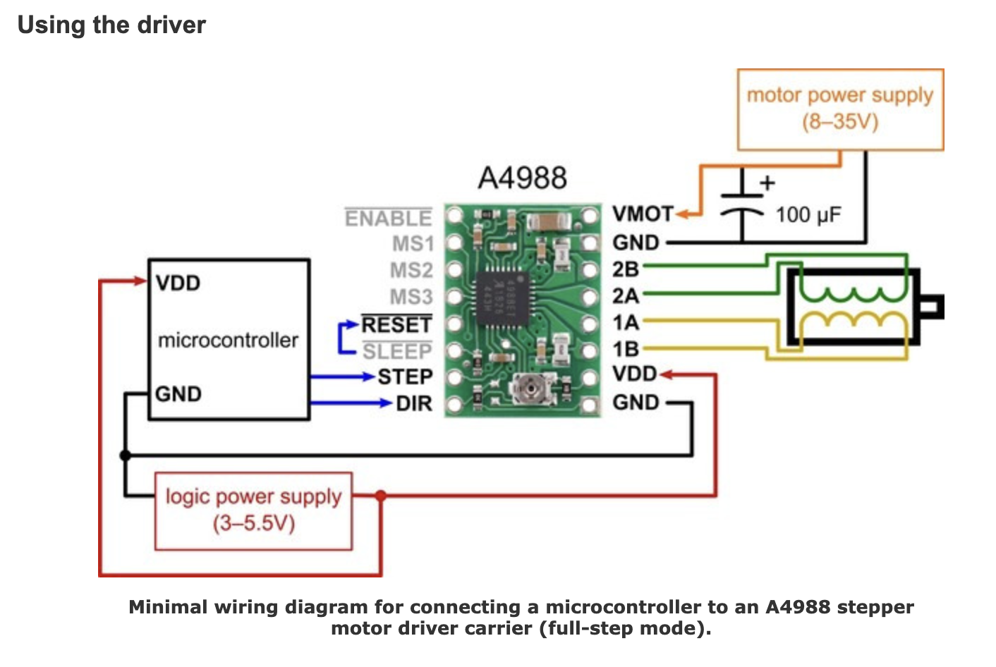
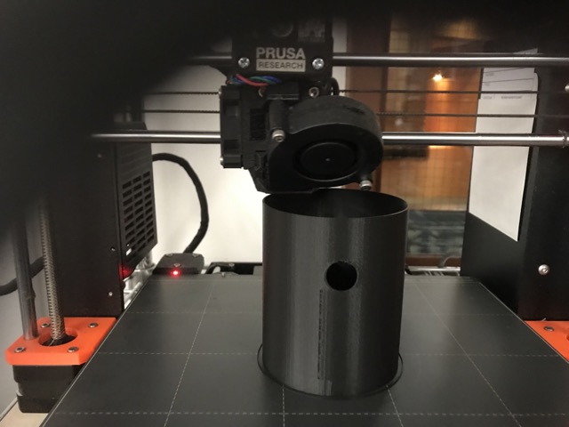
//As for the Zaxis class, the range of motion is greatly
//inspired by how 3D printers use lead screws + nut to go up
//and down. When it is the high speed setting, there
//be a less of a delay in the stepper motor. When it is the
//low speed setting, there will be a bigger delay in the step
//sequence of the stepper motor.
//Below is the class Button:
int interval = 1000;
class Button{
//Establish my member variables:
int buttonPin;
int buttonState;
//Constructor
public:
Button(int pin){
buttonPin = pin; //This will let my microcontroller know
//pin the button is connected to.
pinMode(buttonPin, INPUT_PULLUP);
buttonState = HIGH; //I am starting off saying that
//e button is off, or not pressed.
}
int Update(){
buttonState = digitalRead(buttonPin); //I want to know
//the on/off status of my buttons.
return buttonState;
}
};
//Below is the class Zaxis:
class Zaxis{
//Establish my member variables:
int mstepPin; //Apparently, there are many ways to set my member variables.
//https://stackoverflow.com/questions/10198046/c-member-variables
//This site talks about the pro's and con's of three different methods, and I
//chose the method below:
//void A::setNumber(int number){mNumber = number;}
//so that is why you see mstepPin and mdirPin and see it be set by stepPin and dirPin int
//later in the constructor.
int mdirPin;
bool highspeed;
bool lowspeed;
unsigned long updateInterval; //I didn't know how to make it so that
//if the pestle reached the mortar then it would go back up,
//so for now, I am just putting in an interval, and telling
//it to go up 1 second and down 1 second and repeat.
unsigned long previousMillis;
//to avoid delays, I am invoking millis.
//Constructor
public:
Zaxis (int stepPin, int dirPin, long interval){
updateInterval = 1000;
previousMillis = 0;
mstepPin = stepPin;
mdirPin = dirPin;
pinMode(mstepPin, OUTPUT);
pinMode(mdirPin, OUTPUT);
highspeed = false; //I am putting my initial
//bool values at false. At the very beginning
lowspeed = false; // neither speed settings are being
//indicated until a button is pressed.
}
void Quicker(bool value) {
highspeed = value;
}
void Slower(bool value){
lowspeed = value;
}
void Open(int speed) {
unsigned long currentMillis = millis();
if (speed > 0) {
digitalWrite(mstepPin, LOW);
delay(speed);
digitalWrite(mstepPin, HIGH);
delay(speed);
}
else{
digitalWrite(mstepPin, LOW);
}
//if the reached a second, the stepper motor will turn the other way
if(currentMillis - previousMillis > interval) {
previousMillis = millis();
if (digitalRead(mdirPin) == LOW) {
digitalWrite(mdirPin, HIGH);
}
else {
digitalWrite(mdirPin, LOW);
}
}
}
};
//Now that I have defined my classes, I can then use them:
Button button1(5); //one button is connected to pin 5
Button button2(7); // one button is connected to pin 6
Zaxis pestle(13,12,1000); //stepPin is connected to pin 13,
//dirPin is connected to pin 12
//interval is 1000 ms.
int speed;
void setup() {
//I am using a serial monitor to see which buttons I have pressed
}
void loop () {
// Serial.print("Button 1: ");
// Serial.print(button1.Update());
// Serial.print(" Button 2: ");
// Serial.println(button2.Update());
//below is the logic: if both buttons are pressed, high speed.
//If only button 1 is pressed, low speed.
//Anything else: either only button 2 is pressed, or none is pressed,
//the speed settings are false.
//In the next stage of this project, just button 2 is another speed setting.
//I also need to find a way to make my stepper motor stop moving
if(button1.Update() == LOW ){ //== LOW && button2.Update() == LOW){
// pestle.Slower(false);
// pestle.Quicker(true);
speed = 1;
}
else if(button2.Update() == LOW ){ //== LOW && button2.Update() == HIGH){
// pestle.Slower(true);
// pestle.Quicker(false);
speed = 10;
}
else{
// pestle.Slower(false);
// pestle.Quicker(false);
speed = 0;
}
pestle.Open(speed);
}